
Apologies for the rather long time between updates. I have been rather busy with other things. But I have not been ignoring the 3D printer.
I have made quite a few upgrades and I’m now very happy with the reliability. It did go through a period of stopping during a print which I put down to the original PSU being not very good. This was not a surprise really, it was super cheap!
The options are to get a better 12V PSU or go for a 24V upgrade. The decision was made for me as I managed to pick up a 40A 24V PSU that was being thrown away.

It is a bit noisy though! However it doesn’t even get warm.
A 24V upgrade needs a number of new parts. I needed to get a new hot bed, a new hot end heater cartridge and a pair of external MOSFET boards as applying 24V directly to the main control PCB would result in smoke.
While I was going this I decided to go for a higher wattage hot bed and heater cartridge. The heater came from ebay and is rated 60W compared to the original 40W heater. Unfortunately it was 0.2mm under size on the diameter (again, not a surprise) but 2 wraps of copper tape made for a snug fit. Sorry no pics.
The new hot bed came from Makerbase and is rated 220W. The original 12V hot bed is about 110-120W. This is probably the best upgrade so far as trying to run any material that needed a high temperature bed ended up with it running almost 100% duty cycle, even with an insulated underside.

I’ve also fitted a PEI build surface. I was given some of these by a colleague as I’d helped him with his 3D printer.
Under the hot bed is a new support frame. The original is pretty flimsy so I went with a nice machined one. This required spacers between the bearing blocks and the frame to it would clear the Y axis stepper.

A pair of external MOSFETs are now mounted under the control PCB along with a 30A fuse I had  spare.
Another upgrade is optical end stops. I do sort of miss the *click-click* as it zero’d each axis but these are more repeatable and don’t move.

I also made a custom Y axis stepper mount. The original is pretty flexible and was only held on by 2 screws.

This one clamps over the centre threaded rod I added and also screws to the base board. You can also see the rubber isolating mount for the stepper. I have these on all the steppers now and wow it is SO much quieter.
I replaced the original hot end fan and extruder cooling fan with some nice big radial fans.

These run quite slowly and are almost inaudible unless the cooling needs 100%. The hot end fan has a 56ohm resistor in series as it does not need to run at full speed. The air flow is much higher than the original 30mm fan it came with.
You can also see the cable chain that now feeds the X axis carriage. I made a little PCB from stripboard that terminates all the wiring so I can change things without having to thread the wires all the way back to the control PCB.
My biggest gripe with the Prusa design is the way you can get the Z axis leadscrews out of step with each other. The Anet A8 comes with quad start leadscrews which move 8mm for a single turn. It doesn’t take much force on the Z assembly to get one of them to turn slightly.
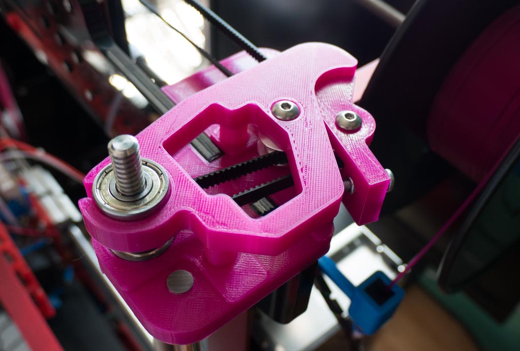
So I now have a belt that links the tops of the leadscrews! A couple of minor cockups happened though.

The top of the leadscrew is supported by 2 bearings so that the belt tension is not trying to bend the leadscrew.
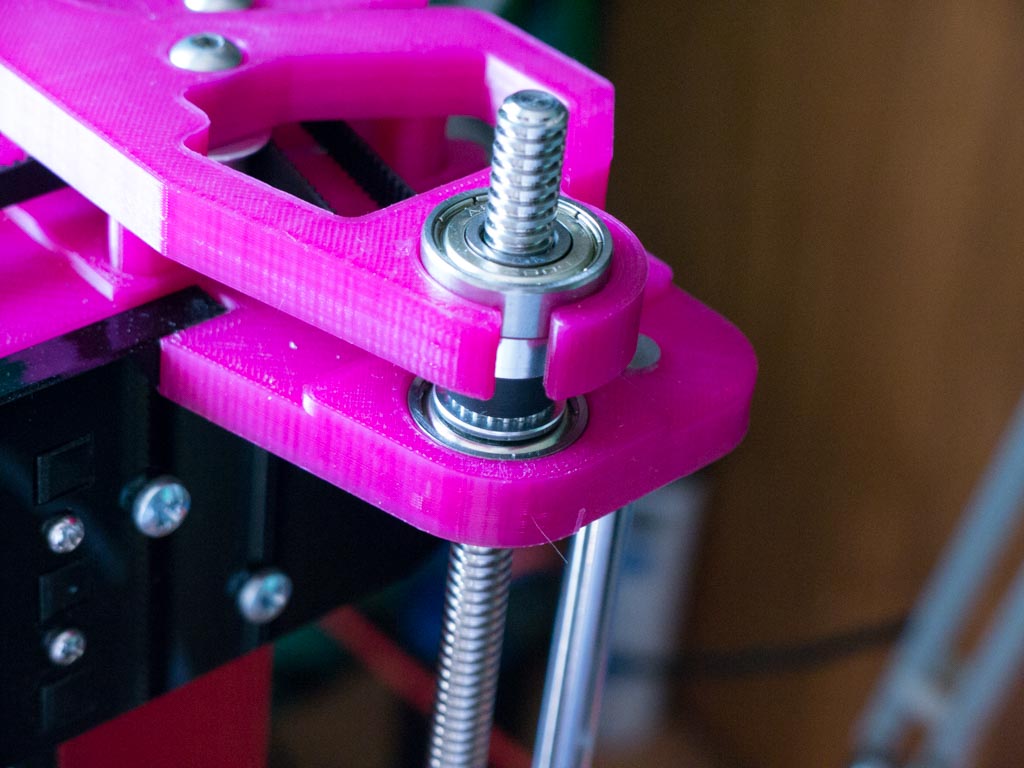
2 idlers guide the belt around the back of the screen and also give tension. The bearings, idlers, toothed pulley for the top of the leadscrew and the belt all came from ebay. GT2 belts come in a small range of sizes so it was pretty much designed around a sensible belt length.
The 2 cockups are that I ordered single start leadscrews by mistake and one of them got bent in the post. I needed 400m long leadscrews to fit the pulley assembly and I picked them based on the image on ebay. But there was a note at the end of the description that said ‘single start thread’ and I ignored that… DOH! This was an easy fix as I just multiplied the Z axis steps per unit by 4. The bent leadscrew is a right pain as it causes the Z axis carriage to rock. Something to fix later!
But I have made some parts which are for other projects. I’ve made myself a Pi based squeezebox player for my garage and made various sized solar filter holders for my trip to the USA to see the total eclipse of the sun.

I need to write up a post on the squeezebox client as it took some work to find all the details needed to make it work. It has a 40×2 LCD and an IR remote control.